CV
View or download my current CV.
PDF previews do not scroll reliably on iPhone. Open the PDF to view every page.
I am a Bilkent graduate Electrical and Electronics Engineering student with a passion for RF systems, signal processing, and machine learning.
I am an Electrical and Electronics Engineering student at Bilkent University, with a strong focus on signal processing, RF systems, embedded systems, digital systems design, and machine learning. During my undergraduate studies, I worked on projects across several areas of electrical engineering, including microprocessor-based systems, digital design, antenna engineering, error-correction codes, neural networks, and RF-based detection systems.
My recent work has increasingly focused on the combination of RF systems, signal processing and machine learning. In my graduation project, developed in collaboration with Meteksan Defense, I worked on deep-learning-based frequency-domain drone detection, where RF signals are analyzed and classified using both classical signal processing methods and learning-based approaches. I also gained industry experience through internships at Meteksan Defense, ADHOC Technology, and ASELSAN, working on topics such as Reed-Solomon codes, CRC implementation, Ethernet physical layer protocols, radar signals, and signal processing applications.
My interests extend beyond engineering into both creative and interdisciplinary areas. I am interested in music, psychology, neuroscience, photography, and visual design, as well as topics that connect technical systems with human perception and cognition. My minor in Psychology has also shaped the way I think about learning, behavior, and intelligent systems, complementing my technical background in signal processing and machine learning.
I also enjoy playing the piano, guitar, and violin, along with photography, origami, and cycling. Through my work at Radio Bilkent as a broadcaster and Assistant Music Director, I have been involved in live broadcasting, music programming, and content curation, which helped me develop communication skills alongside my engineering work.
During my time at Bilkent University, I was actively involved in Radio Bilkent as a part of the Music Department. We controlled the songs played on the radio, as well as the songs played at our sponsors' events, school events etc. I regularly hosted talk shows called "Drive Time" at prime time in addition to other talk shows and music/genre broadcasts at various hours.
Contact
If you would like to reach out about projects, graduate opportunities, internships, or collaborations, you can send me a message here.
Documents
My curriculum vitae and my undergraduate transcript from Bilkent University are provided.
View or download my current CV.
PDF previews do not scroll reliably on iPhone. Open the PDF to view every page.
View or download my transcript.
PDF previews do not scroll reliably on iPhone. Open the PDF to view every page.
Portfolio
Here are some of my projects that I have completed successfully during my undergraduate studies. The reports, presentations, repositories, and other materials related to the projects are provided in the links below each project description to provide detailed information.
Undergraduate senior project conducted with the consultancy of Meteksan Defense.
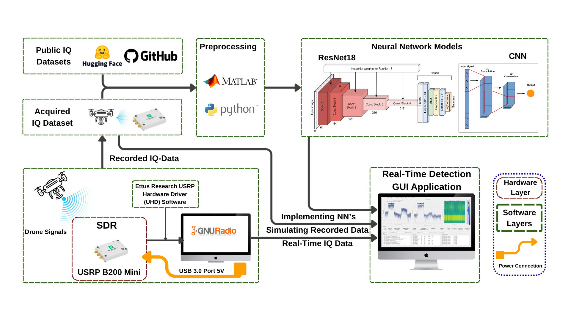
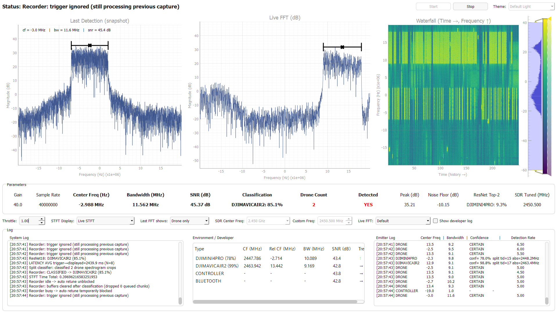
This project focuses on the real-time detection and identification of drones using RF signals. As commercial UAVs become more common, detecting unauthorized drones in crowded 2.4 GHz and 5.8 GHz ISM bands has become an important security and spectrum-monitoring problem. The system was designed to distinguish drone signals from Wi-Fi, Bluetooth, and other non-drone emitters, estimate signal parameters such as center frequency and bandwidth, and classify different drone models through a real-time graphical interface. The main requirements included real-time operation, reliable detection under interference, accurate drone classification, and practical deployment using SDR hardware such as the USRP B200mini.
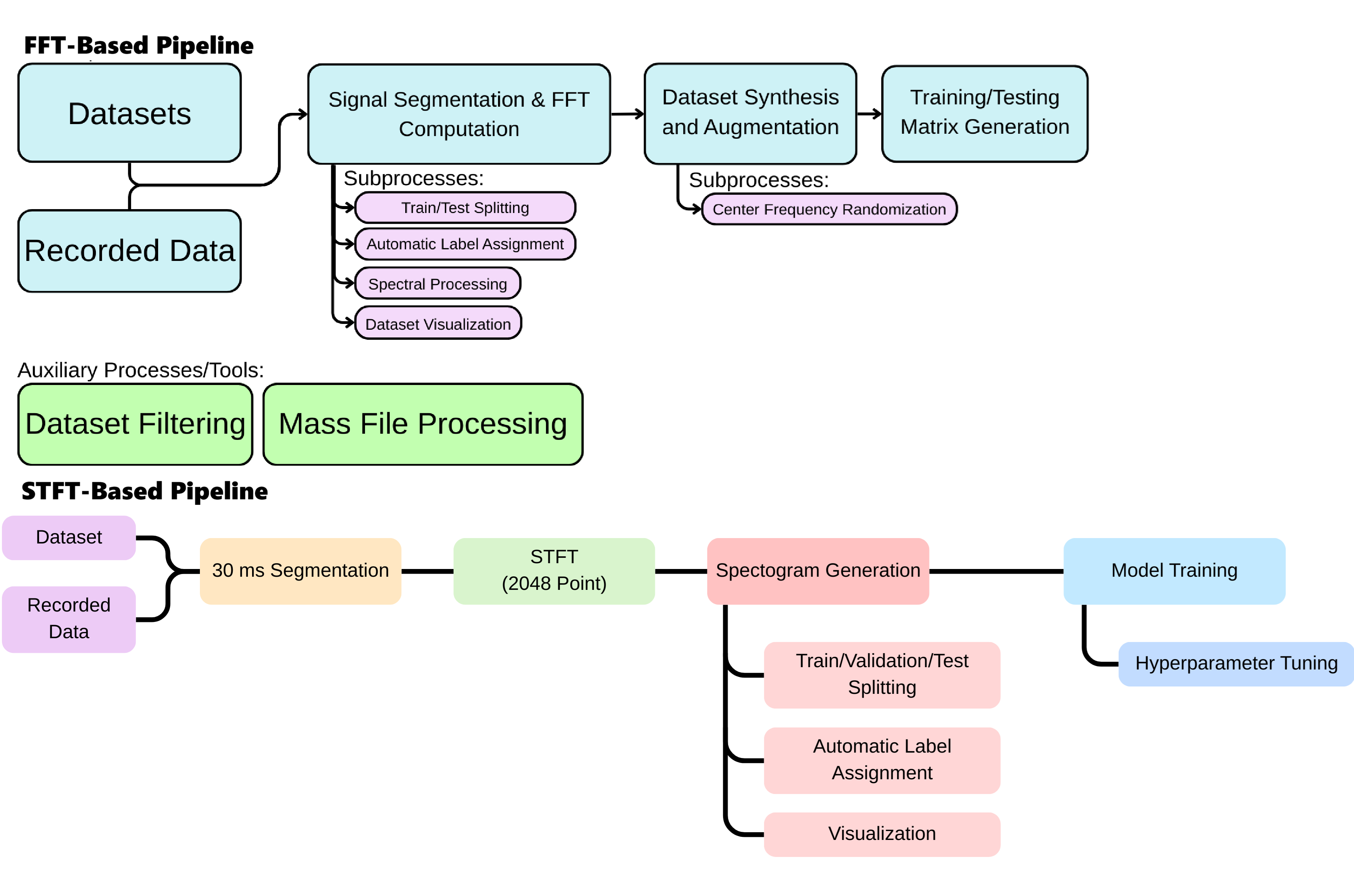
The project combines classical signal processing and deep learning methods. Raw IQ samples are processed using FFT-based spectral analysis and STFT-based time-frequency representations. The FFT pipeline is used for lightweight signal detection, signal parameter extraction, and fast spectral analysis, while STFT spectrograms are used as image-like inputs for CNN-based drone classification. Different neural network architectures were tested for classification, and the system was integrated into a Python-based real-time GUI that displays the spectrum, spectrogram, detected emitters, signal parameters, and classification outputs.
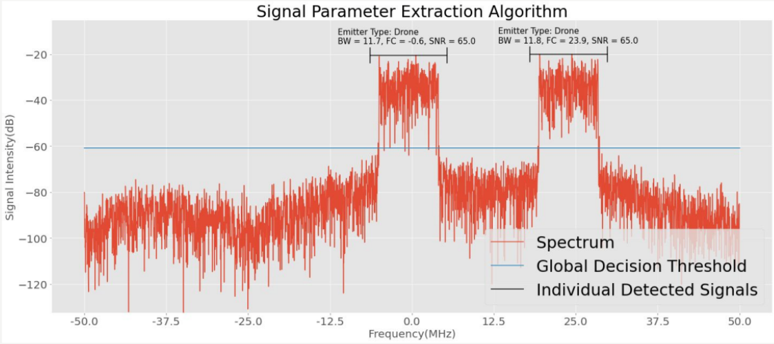
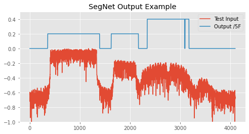
A major contribution of the project was the implementation of several detection and classification algorithms from scratch, including multiple-emitter detection, signal parameter extraction, FFT-based classification, and a SegNet-style FFT-bin classification model. The multiple detection algorithm was designed to separate overlapping drone, controller, Wi-Fi, and Bluetooth-like signals in the spectrum and estimate their center frequencies and bandwidths. In parallel, the SegNet-based model classified each FFT bin into signal categories, allowing the system to visualize signal regions directly across the spectrum. The two figures included in this section show the outputs of the SegNet model and the custom multiple detection algorithm, demonstrating how the system separates complex RF scenes into meaningful emitter regions.
The final system achieved strong performance in both detection and classification tasks while remaining suitable for real-time operation. The FFT-based model reached an overall accuracy of 99.78%, with class-wise F1-scores of 100.00% for noise, 99.68% for drone, and 99.60% for Wi-Fi, showing that the system could reliably distinguish drone activity from common non-drone RF signals. False alarm behavior was also evaluated in an 8-hour crowded Wi-Fi environment: although the system produced internal false positives, the Temporal Consistency Filtering mechanism suppressed almost all of them, resulting in only 0.1 false positive alerts per hour and 0 critical false negatives. Timing tests showed average end-to-end latencies of 127.43 ms for detection, 1818.8 ms for classification, and 2849 ms for multiple detection, satisfying the real-time requirements for the main detection and classification pipeline. The STFT-based models also performed strongly in GUI-integrated field tests, with ResNet-based models reaching around 98.8–99.0% field-test accuracy, while lightweight or transformer-based alternatives showed that deployment performance depends not only on offline accuracy but also on stability, latency, and robustness under real RF conditions. Overall, the project demonstrated that a hybrid FFT/STFT pipeline can provide accurate drone detection, low false alarm output, reliable classification, and practical real-time visualization in crowded wireless environments.
Antenna designing & manufacturing project from recycled materials for Antenna Engineering course.
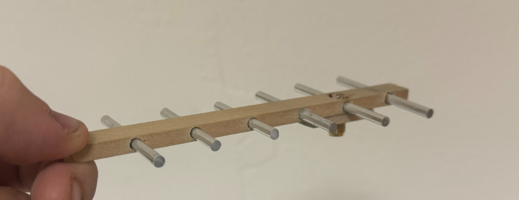
This project focused on the design, simulation, fabrication, and experimental validation of a 3 GHz Yagi-Uda antenna for the EEE-452 Antenna Engineering course. In the initial stage, both conventional 3-D Yagi-Uda and quasi Yagi-Uda configurations were investigated using CST simulations. Although both designs were simulated and optimized, the conventional 3-D Yagi-Uda antenna was selected for hardware implementation because it provided better impedance matching, higher directivity, and a larger tolerance margin for fabrication errors. The final antenna used a reflector, driven element, and multiple directors, with the element lengths and spacings optimized to achieve resonance near 3 GHz. A notable aspect of the project was that the antenna was manufactured entirely from recycled or scrap materials, including a wooden boom, aluminum rods from broken camping tents, and SMA connectors provided by the department, resulting in a total material cost of 0₺.
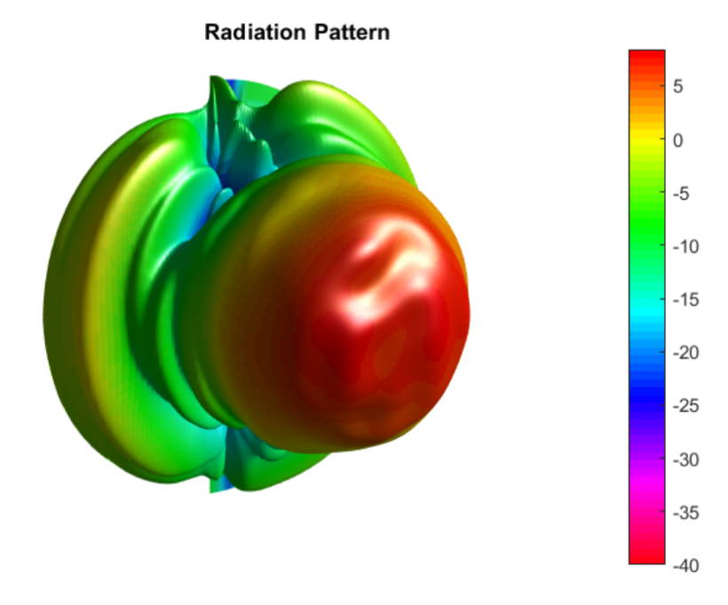
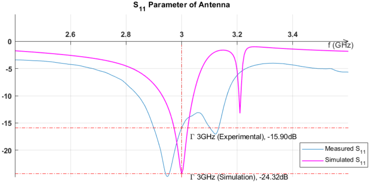
The fabricated antenna was tested through both S₁₁ measurements and radiation pattern measurements. The measured S₁₁ response showed that the antenna was successfully tuned around 3 GHz, although the resonance became broader compared to simulation due to losses in the physical implementation. Radiation pattern measurements were carried out in an anechoic chamber at METEKSAN Defence using near-field measurement methods. At 3 GHz, the antenna achieved a measured maximum directivity of approximately 11.49 dBi, with E-plane and H-plane HPBW values of 52.73°, which were generally consistent with the simulation and theoretical expectations. Some discrepancies were observed in radiation efficiency, cross-polarization, and the direction of maximum radiation. These differences were mainly attributed to feedline losses, SMA connection losses, mounting effects, backlobe reflections, and possible measurement alignment errors. Overall, the project successfully demonstrated the complete antenna engineering workflow, from simulation-based design to low-cost fabrication and experimental verification.
This Electromagnetic Pulse generator was designed for EEE 351 - Engineering Electromagnetics course.
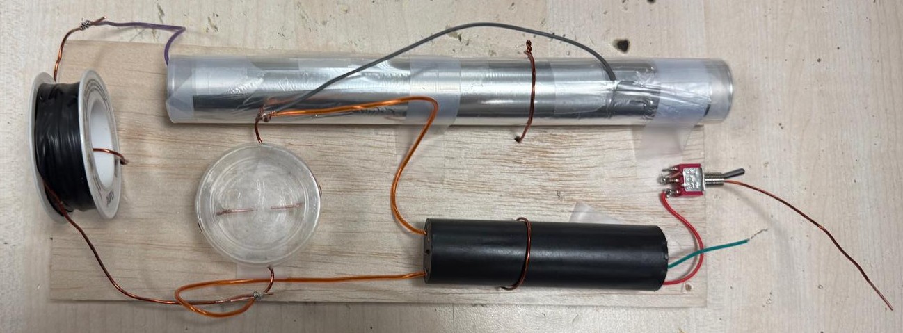
This project focuses on the design and implementation of a small-scale Electromagnetic Pulse (EMP) generator. The main goal was to create a short burst of electromagnetic energy using a high-voltage boost converter, a capacitor, a spark gap, and a radiating coil. The capacitor stores electrical energy and discharges it rapidly through the coil when the spark gap breaks down, producing a sudden current spike and a corresponding electromagnetic disturbance. The theoretical background of the project was based on RLC circuit behavior, magnetic field generation through a coil, and the relationship between spark gap distance, pulse intensity, and firing rate.
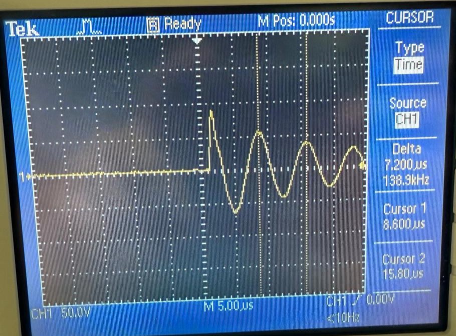
During the development process, the main components were built and tested separately, including the capacitor, spark plug, radiating coil, and coherer. The final prototype was assembled according to the circuit schematic and tested using both measurement equipment and practical demonstrations. The measured induced voltage had a frequency of 139 kHz, which was close to the theoretical value of 150 kHz, giving an error of about 7.3%. Additional tests with a calculator and a coherer showed that the device was able to create observable electromagnetic interference, confirming that the EMP generator operated as intended.
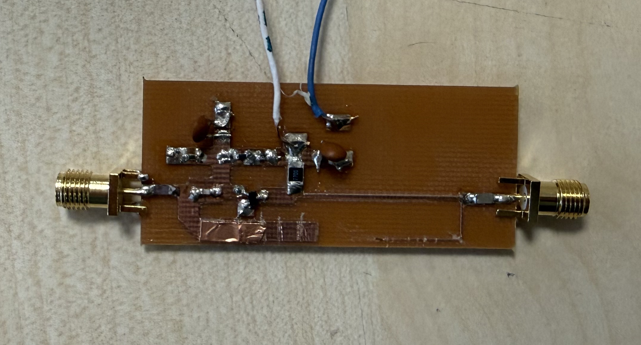
Design & implementation of a high gain amplifier as a part of our microwave electronics course.
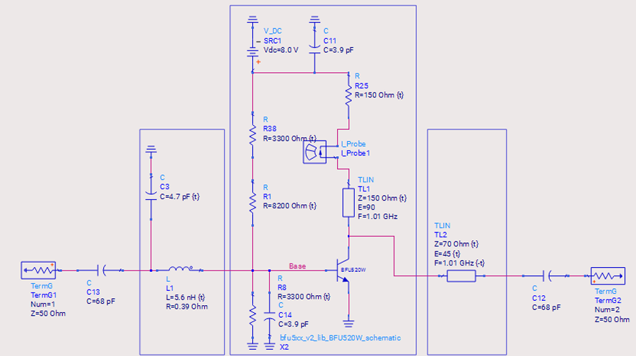
This project focuses on the design, simulation, layout conversion, and measurement of a high-gain amplifier (HGA) operating at a center frequency of 1.01 GHz, corresponding to the required operating band of approximately 960 MHz to 1060 MHz. The main goal was to obtain sufficient gain while maintaining proper impedance matching and stable operation across the band. According to the report, the amplifier was required to provide at least 12.44 dB gain, and the simulated design achieved a gain above this value, with the initial simulation showing S21 > 13.65 dB. The amplifier also satisfied the input and output return loss requirements, since both S11 and S22 were below −12 dB in the operating band, meaning that the input and output ports were reasonably well matched to 50 Ω. In addition, the stability factor was greater than 1 in the initial design, indicating unconditional stability over the analyzed frequency range.
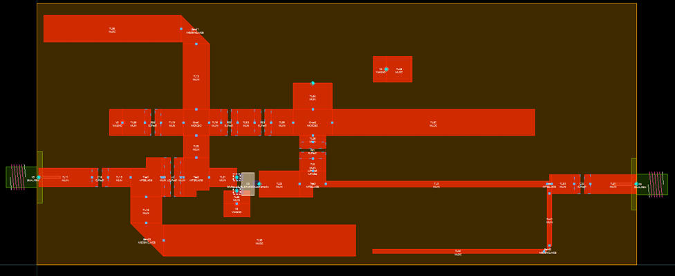
The design process included a biasing network with resistors, bypass capacitors, and transmission lines so that the DC biasing components would not disturb the RF signal at 1.01 GHz. DC-blocking capacitors were added at the input and output, and the input/output ports were matched to 50 Ω using matching networks: an L-section network with a shunt capacitor and series inductor at the input, and a transmission-line-based output matching network. During the layout-compatible version, the schematic was adapted by replacing transmission lines with microstrip lines, converting lumped components to layout-compatible elements, and compensating for parasitic effects. The final layout-compatible simulation still satisfied the key requirements: S11 and S22 < −12 dB, gain greater than 12.44 dB, maximum gain variation of about 0.854 dB, and an operating point of 18 mA collector current with 3.2 V collector voltage from an 8 V supply.
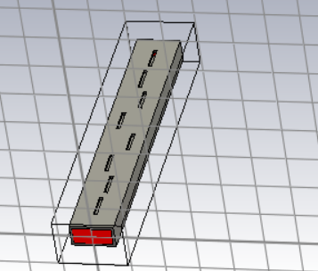
This project involved the design and simulation of a slotted waveguide antenna for operation at 10 GHz, as part of our advanced antenna design course.
This project focuses on the design of an 8-slot longitudinal slotted waveguide antenna operating at X-band, with 10 GHz selected as the design frequency. The antenna uses a WR-90 waveguide and places non-uniform longitudinal slots on the broad wall of the waveguide. Since the waveguide operates in TE₁₀ mode, the radiation strength of each slot can be controlled by adjusting its offset from the centerline. This makes the antenna behave like a non-uniform array, allowing the sidelobe level to be reduced. The main design requirement was to achieve a sidelobe level below −30 dB, so different amplitude distributions were compared, and the Taylor distribution was selected because it satisfies the sidelobe requirement while keeping the main lobe relatively narrow.
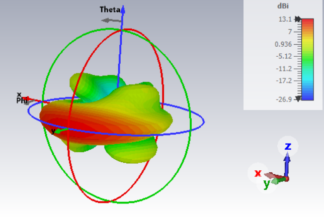
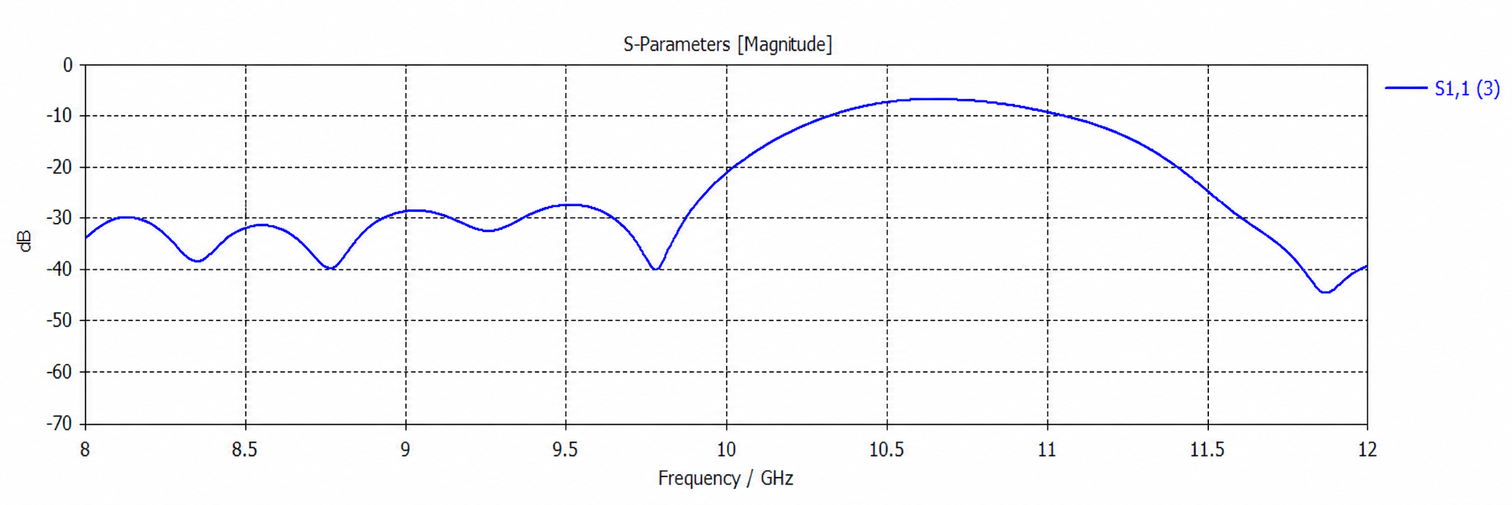
The antenna was implemented and optimized in CST, where the slot offsets were tuned while preserving the excitation ratios determined by the Taylor distribution. The impedance matching was handled through CST optimization rather than being calculated manually. The final radiation pattern shows a main lobe magnitude of about 13.1 dB, an angular width of approximately 18 degrees, and a sidelobe level around −35.4 dB, meaning the design successfully meets the sidelobe requirement. The final S₁₁ result also indicates that the antenna is matched around the intended operating frequency of 10 GHz. Overall, the project demonstrates that a properly tapered slotted waveguide array can provide high gain, directional radiation, and low sidelobe performance at X-band.
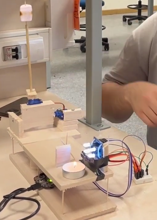
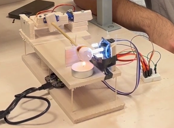
This project was my project for our embedded systems and microcontrollers course and was implemented using C.
his project implements an automatic marshmallow roaster using an MKL25Z microcontroller, a TCS3200 color sensor, servo motors, RGB LEDs, a buzzer, and user input buttons/switches. The system continuously measures the marshmallow’s color by sampling red, green, blue, and clear light responses from the color sensor, then normalizes these values to estimate the roasting level. While the marshmallow is being roasted, one servo positions it near the fire and another servo slowly rotates it to achieve more even heating. The RGB LEDs are updated according to the detected color, giving a visual indication of the current roast state. When the code detects that the marshmallow has reached the desired color threshold, or when the user manually presses the button, the system moves the marshmallow away from the fire, activates the buzzer, and enters a finished state. A second button press resets the mechanism and starts the roasting cycle again.
Interactive Tools
Small browser-based applications and visual experiments are collected here.
An application that converts curves to Minecraft block patterns.
Practice Turkish city plate numbers in both directions.